|
|
Home >Online Product Documentation >Table of Contents >Symbols for WSDL Elements Symbols for WSDL ElementsEach element in a WSDL document displayed in the diagram pane is represented by its own symbol; tool tips, which are displayed when you hover over a node in the diagram, identify the node's type (binding, service, and so on). The symbols used in the diagram are summarized in Table 112. Nodes can be expanded and collapsed using the plus and minus symbols, respectively, that appear on the right side of the node. In Figure 446, for example, the Part1 Message Part has been expanded; the certifyContactRequestMessage Message has not. Symbols for XML Schema ElementsThe WSDL Editor diagram pane displays symbols for XML Schema elements if you have a Schema element defined in your WSDL document. See Table 1 for more information about symbols for XML Schema elements. See The Types Element to learn more about using XML Schema in a WSDL. Displaying Element DetailsTo streamline the diagram, most elements are displayed with their details hidden by default. You can change the settings
l For all WSDL documents using the WSDL Details page on the Options dialog box.
l For the current WSDL document using the Schema Diagram Properties dialog box. Using the Schema Diagram Properties dialog box overrides the default settings set using the Options dialog box.
The mechanics of changing display settings are the same, regardless of where you change them. For each node property, you can choose to
l Show the property
l Show the property only if it is not empty (that is, it has not been defined)
l Hide the node
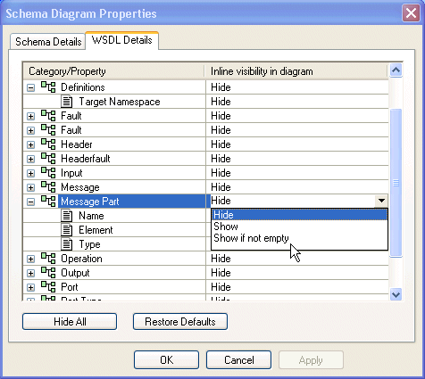
If all of an element's properties have the same show/hide setting, that value is displayed in the Inline Visibility in Diagram field. If no value is displayed in the Inline Visibility in Diagram field, it means that two or more properties have different show/hide settings. You can change the display for classes of elements (all Message Parts, for example) using the Schema Diagram Properties dialog box, shown in Figure 449. (The Properties window, which appears to the left of the Diagram tab, displays all the properties for any node you select.)
To display the WSDL Details page of the Options dialog box:
1. Select Tools > Options from the Stylus Studio menu.
2. Navigate the Module Settings > WSDL Editor branch and click WSDL Details.
To display the Schema Diagram Properties dialog box:
l Select Diagram > Properties from the Stylus Studio menu.
l Select Properties from the diagram shortcut menu.
To change element properties display:
1. Display the either the Schema Diagram Properties dialog box, or the WSDL Details page of the Options dialog box.
2. Select the element whose properties display you want to change.
3. Click OK.
|
XML PRODUCTIVITY THROUGH INNOVATION ™

 Cart
Cart


